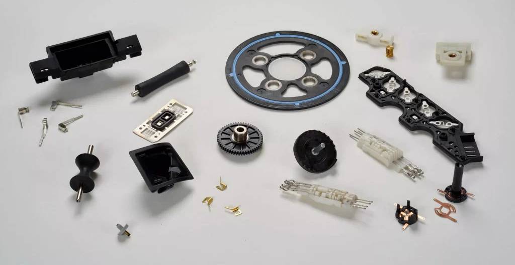
A professional injection molding supplier improves product development by finding manufacturability problems before steel is cut, matching resin behavior to part geometry, and building tooling around real production volume. A useful DFM review checks wall thickness, draft, ribs, bosses, undercuts, gates, ejection, tolerances, and cosmetic surfaces. Rib thickness is commonly kept around 40–60% of the adjoining wall, while draft often starts near 1° for smooth surfaces. ISO 20457:2026 provides a plastics-specific framework for dimensional and geometrical tolerances. Early supplier work can reduce mold revisions, shorten qualification, control scrap, and make the move from prototype quantities to 100,000+ molded parts easier to manage.
A CAD model can pass functional review and still be expensive to mold. Plastic changes dimensions as it cools, thick sections cool more slowly than thin ones, and a feature that works in a machined prototype may require slides, lifters, inserts, or a different parting line in a production mold. For that reason, supplier involvement is more useful before the drawing is frozen than after the mold has already been machined.
The first engineering pass should compare geometry with the selected resin. ABS parts, for example, are commonly designed within a wall range of roughly 1.14–3.50 mm, while polypropylene can often work across about 0.64–3.81 mm, depending on flow length, geometry, appearance, and mechanical requirements. Published molding guidance also places rib thickness at about 40–60% of the surrounding wall to reduce sink and uneven cooling.
That wall review leads naturally to transitions between sections. A housing with a 2.0 mm wall beside a solid 6 mm boss base may show a visible sink mark because the heavier section stays hot longer. Coring the boss and supporting it with thinner gussets keeps more of the part near the same cooling rate without simply adding plastic.
A supplier should ask where material can be removed before asking where more material should be added. Extra thickness often increases cooling time and part weight without giving the expected improvement in stiffness.
Draft comes next because molded parts have to leave the steel cleanly thousands of times. A common starting range is about 1–2° for ordinary molded walls, while deeper textures normally need more clearance; Covestro guidance also gives at least 0.5° for many PC-based materials and recommends about 1° where the design permits easier ejection. A part with insufficient draft may still produce samples, but repeated production can show scuffing, drag marks, higher ejection force, or unstable cosmetic quality.
Once the basic geometry is moldable, the supplier can examine features that add tooling operations. One internal undercut may require a side action; several undercuts can increase mold size, machining work, maintenance points, and molding sequence complexity. Removing an unnecessary undercut before tooling can therefore matter more than negotiating a small reduction in the quoted piece price.
A practical DFM review should normally cover at least the following items:
-
wall consistency and heavy material sections;
-
40–60% rib and boss-wall relationships where suitable;
-
draft on walls, ribs, bosses, holes, and textured surfaces;
-
parting-line placement and shutoff geometry;
-
undercuts that require slides, lifters, or removable inserts;
-
ejector-pin locations and acceptable witness marks;
-
gate position, gate vestige, weld lines, and air traps;
-
dimensions that require tighter control than surrounding features.
Those checks become more useful when the supplier knows the production target. A mold intended for 5,000 parts per year does not need the same cavity layout, automation level, cooling system, steel selection, or runner arrangement as a program expecting 1,000,000 parts annually. A low-volume tool may favor lower initial spending, while a high-volume program can justify more cavities, stronger wear surfaces, replaceable inserts, and more developed cooling.
Production volume also changes how cycle time should be viewed. On a 1,000,000-part program, reducing a 30-second cycle to 27 seconds cuts molding time by 10%. In a single-cavity example, that is about 833 machine hours versus 750 hours before downtime, maintenance, and changeovers are considered. Cooling layout, runner design, gate size, part thickness, and ejection therefore belong in product-development discussions rather than being left entirely to the production floor.
| Development item | Supplier input | Production issue it can reduce |
|---|---|---|
| Wall and rib geometry | Maintain suitable section ratios; ribs often around 40–60% of the wall | Sink, warp, long cooling |
| Draft | Start near 1° where geometry and finish allow | Scuffing, sticking, ejection marks |
| Gate location | Review flow path and visible gate areas | Weld lines, poor filling, cosmetic marks |
| Undercuts | Remove or simplify where function allows | More slides, mold size, maintenance |
| Tolerances | Apply tighter limits mainly to functional interfaces | Scrap, inspection time, repeated tool correction |
Tolerance review becomes the next step because plastic dimensions cannot be treated like machined metal dimensions. ISO 20457:2026, published in August 2026 as a 34-page second edition, covers geometrical and dimensional tolerances and acceptance conditions for molded plastic parts. It recognizes variation associated with shrinkage, geometry, processing conditions, warpage, and non-uniform cooling.
A supplier can therefore separate a dimension that affects sealing, bearing alignment, snap engagement, or assembly from one that only defines a nonfunctional surface. Putting ±0.05 mm on every dimension may make a drawing look precise, but polymers, part size, mold temperature, cavity position, fiber orientation, and measurement conditions all affect repeatability. Tighter specifications should have a functional reason and an agreed measurement method.
Material selection then has to be checked against the same geometry rather than handled as a separate purchasing task. Polypropylene, ABS, polycarbonate, nylon, acetal, PMMA, and glass-filled grades differ in flow, shrinkage, moisture sensitivity, surface finish, stiffness, and molding temperature. A resin chosen from tensile-strength data alone can behave poorly when molded into a thin, long-flow enclosure.
Glass reinforcement illustrates the tradeoff. Adding glass fiber can increase stiffness and improve dimensional behavior in some directions, yet fiber orientation can also produce different shrinkage along and across the flow path. A supplier should review gate position and expected flow direction before a glass-filled material is approved for a flat housing where warpage is tightly limited.
That material review connects with gate and runner design. A gate controls where molten resin enters the cavity, so its position affects filling pressure, weld-line placement, packing, cosmetic marks, and flow orientation. Moving one gate by several millimeters can alter where two flow fronts meet around a hole or boss, which matters when the meeting area carries mechanical stress.
Mold-flow software is most useful when it answers a manufacturing question: where filling becomes difficult, where weld lines may appear, how pressure changes across the cavity, or whether another gate position deserves evaluation.
Simulation should still be checked against molding trials. The first tool trial provides physical information on filling, flash, short shots, sink, warpage, ejection, gate appearance, dimensions, and cycle conditions. Rather than changing several settings at once, an experienced molder records barrel temperatures, mold temperature, injection speed, transfer position, holding pressure, holding time, and cooling time so later adjustments have a stable reference.
Sample quantity should match what is being checked. Ten parts may be enough for an early visual review but are weak support for judging production consistency. For dimensional studies, a supplier may measure 30 or more molded samples across cavities and time intervals, then examine whether readings cluster near the nominal specification or move with cavity position and process conditions.
The tooling team can use those measurements to separate a steel issue from a process issue. If one cavity repeatedly produces a dimension 0.15 mm larger while the other cavities stay centered, the mold should be inspected before broad machine adjustments are made. If all cavities move together as mold temperature changes, process settings and thermal conditions deserve more attention.
Inspection planning should be settled before production release as well. A molded housing may contain 60 drawing dimensions, but perhaps only 8 affect assembly or product function. Measuring the same 8 features with agreed datums, gauges, conditioning time, and inspection frequency gives the supplier and product team a clearer production record than treating every drawing dimension as equally significant.
For companies using Industrial injection molding solutions, supplier capability should therefore be judged across engineering and production work, not machine tonnage alone. Useful questions include whether DFM is completed before mold machining, whether gate and ejection locations are reviewed with the customer, how dimensional samples are reported, and how process settings are controlled after the approved trial.
Tool construction should also match expected maintenance. A mold running 20,000 parts has a different service requirement from one planned for several million cycles. Replaceable wear inserts, standardized components, accessible cooling circuits, hardened contact areas, documented spare parts, and preventive maintenance intervals may cost more at tooling release but can reduce production stoppages later.
The same reasoning applies to cavity count. Moving from one cavity to four cavities can increase output per molding cycle by up to 4×, but only when the filling system, cooling, clamp requirement, part handling, and cavity balance support stable production. A poorly balanced four-cavity mold can create more inspection work and scrap than a well-developed two-cavity tool.
Packaging and downstream assembly should be reviewed before the final mold revision. A cosmetic part that meets dimensional inspection can still arrive scratched if parts rub together in bulk packaging. A snap-fit may mold within tolerance yet require excessive assembly force when mating dimensions from two separately produced components stack toward opposite specification limits.
Supplier feedback at this stage can cover molded-part handling, robot removal, degating, inserts, ultrasonic welding, printing, coating, assembly fixtures, and packaging. If a product requires 100,000 assemblies each year, removing even 5 seconds from a manual secondary operation saves about 139 labor hours annually.
Production records then provide information for later revisions. Comparing cycle time, cavity-specific dimensions, reject categories, maintenance frequency, material lot changes, and assembly findings gives engineers a practical basis for the next mold or product version. A supplier that keeps tooling, process, and inspection records can explain why a revision was made in 2026 instead of forcing a new engineering team to reconstruct the history from samples.
The product-development relationship works best when requirements are shared before manufacturing choices become expensive to change. Annual volume, resin, cosmetic surfaces, mating parts, environmental exposure, functional dimensions, expected mold life, secondary operations, and inspection needs should be available during DFM, so the supplier can design the mold around the product that will actually be produced rather than around the CAD file alone.